



The process
Twenty-one stages, and what each one is for.
Redrawn from the company's own printed process chart. Stages 1 to 13 are the micronizer plant; 14 to 21 are the optional coating line that follows it.
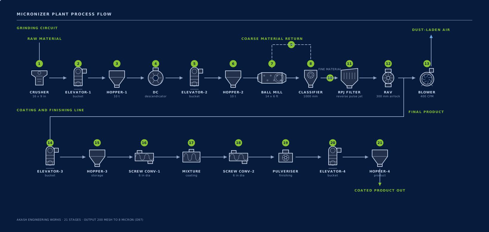
The chart is the company's own; only the rendering is new. Scroll it sideways on a narrow screen, or read the stage list below — it carries the same content.
Stage by stage
What happens, and in what order.
Size reduction
Stages 1–7- 1
CrusherSize reduction
Reduces run-of-mine rock to a feed the mill can take. Jaw crusher, 16 in × 9 in.
- 2
Elevator-1Material handling
Bucket elevator lifts crushed material to the first storage hopper.
- 3
Hopper-1Material handling
Storage hopper buffers the crusher from the rest of the line.
- 4
DescendicatorSize reduction
Beater-type disintegrator. Required to bring 30/80 mesh grains to mill feed size.
- 5
Elevator-2Material handling
Lifts disintegrated material to the mill feed hopper.
- 6
Hopper-2Material handling
10 tonne mill feed hopper, 2000 × 2000 mm, with a screw feeder underneath.
- 7
Ball MillSize reduction
14 ft × 6 ft air-swept ball mill. The grinding stage — everything before it prepares the feed, everything after it separates the product.
Classification
Stages 8–10- 8
ClassifierSeparation
1000 mm high-efficiency dynamic classifier. Cage speed sets the cut point, and so the fineness.
- 9
Coarse returnSeparation
Oversize from the classifier goes straight back to the mill inlet. This is what makes it a closed circuit.
- 10
Fine materialSeparation
Product-size particles travel on in the air stream to the collection stage.
Collection
Stages 11–13- 11
RPJ Bag FilterCollection
Reverse pulse jet filter, cleaned on line, collects the product out of the air.
- 12
Rotary AirlockCollection
300 mm valve discharges the collected powder while holding the pressure difference.
- 13
BlowerCollection
400 CFM centrifugal blower draws the air through the whole circuit.
Coating line — optional
Stages 14–21- 14
Elevator-3Material handling
Coating line begins. Lifts finished powder to the coating feed hopper.
- 15
Hopper-3Material handling
Feed hopper for the coating line.
- 16
Screw Conveyor-1Material handling
6 in screw feeder meters powder into the mixer.
- 17
MixerSurface coating
Powder and molten stearic acid are brought together.
- 18
Screw Conveyor-2Material handling
Carries the treated powder on to the pulveriser.
- 19
PulveriserSize reduction
Breaks any agglomerates formed during coating.
- 20
Elevator-4Material handling
Lifts coated product to final storage.
- 21
Hopper-4Material handling
Finished coated product, ready for packing.
As the works draws it
The same line, from our own CAD assembly.
Each machine named the way the works names it. The chart above is the process; this is the arrangement it is built in.
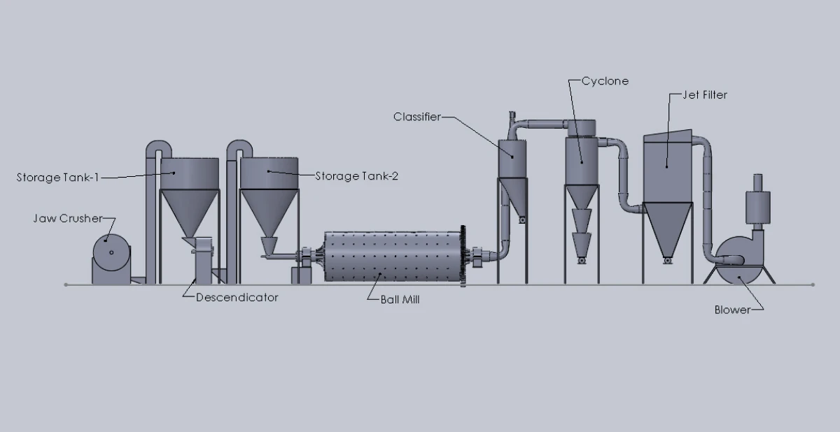
Jaw crusher · storage tank 1 · descendicator · storage tank 2 · ball mill · classifier · cyclone · jet filter · blower.
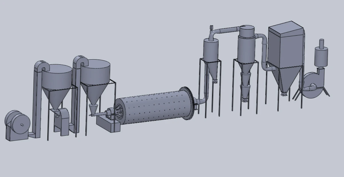
The same assembly rendered from the works' three-dimensional model.
Seen as a machine
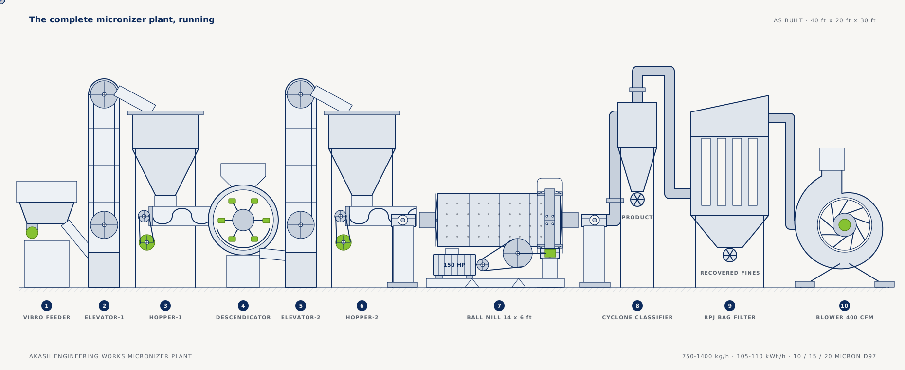
The same twenty-one stages, built.
Every stage in the chart above is a real machine bolted to a real floor. This is the line as it stands, drawn from the company's CAD assembly.
What the site has to provide
Before the erection team arrives.
Space and civil work
A bay of 40 ft long × 20 ft wide × 30 ft high per micronizer plant. The mill foundation is poured by the customer to a dimensioned drawing AEW supplies; the foundation frame is collected from the AEW workshop.
During erection
Roughly seven days on site. The customer provides a 12–14 tonne crane for three of them, plus oxygen, an LPG cylinder and a welding machine, and food and accommodation for the team. Panel, cables and accessories are bought separately.
Want the process sized to your tonnage?
Send us a target fineness and a required output and we will come back with a plant configuration and a scope of supply.